Why Tooling Design is the Key to Precision in HPDC and LPDC Automotive Casting
For automotive engineers responsible for die casting, their focus tends to be on the outcomes of the process.
While that’s to be expected, many overlook the single biggest variable behind those results. Die casting tooling.
The quality of the die determines far more than part geometry in both High-Pressure, Low-Pressure Die-Casting and Gravity-Die-Casting. Die’s are too often thought of as just a mould, whereas engineers should actually be thinking of it as a precision tool that’s designed to balance repeatability with scalable performance.
This need to reframe thinking is even more immediate during a time when OEMs want faster programmes that meet global net zero targets. For lead engineers, getting tooling right at the start de-risks programmes and helps to meet performance targets from day one.
Here, we’ll be exploring the technical considerations behind tooling design and why these decisions need to be made by engineers, not just procurement.
What is Tooling in Die Casting?
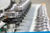
Tooling refers to the design and manufacturing of the reusable steel mould that’s used to repeatedly shape molten metal into parts using extreme pressure.
The die itself isn’t just a hole in which a shape is created. It is far more complex than that. These are precision-engineering systems that often include:
- Cores
- Ejector pins
- Runners
- Cooling channels
- Venting
With so many intricate features, getting the design of these wrong can cause significant dimensional inaccuracies, which have wider knock-on effects on the entire programme. When done poorly, the product can become more porous and reduces tool life expectancy or in some cases can result in the tool having to be scrapped.
When engineered correctly, modern dies can be used repeatedly without sacrificing the consistency of the product, even when subjected to regular, extreme thermal and mechanical stress cycles.
The reliability of these items makes tooling decisions early on in the project so much more important. Get it right, and it’ll reward you. For instance, a well-optimised die can aid better thermal control, which has the knock-on effect of reducing porosity and shrinkage as well as allowing for more reliable repeatability.
Tooling is not a sunk cost, rather a strategic investment that pays off in the form of faster programme cycles that yield higher numbers of products which don’t require rework.
Tooling for High-Pressure Die-Casting (HPDC): Speed and Volume at Scale
HPDC uses hardened steel dies that can withstand the rapid injection forces they face and still meet cycle demand. The dies need to ensure 1000–2000 bar pressures on top of repeated thermal cycling, all without distorting or cracking.
To cope with this, lead engineers choose H13 and SKD61 tool steels because of their thermal fatigue-resistant properties. The value of tooling design is in the way it does, or at least should, anticipate common failure modes like cavity wear.
The tooling in HPDC needs to be designed for:
- Part ejection
- Thermal control
- Internal defects
- Rapid fill
Failure to do so can result in cold shuts and entrapped air. These short fill times, often less than 100 milliseconds, make gating and venting critical, as a poor layout leads to air pockets and weaker part areas.
When engineered correctly and maintained, these tools can exceed 120,000 shots. The health of these dies is influenced by several factors, including the aluminium alloy that’s used. With predictive maintenance and shot-by-shot monitoring, it’s possible to extend the life of the dies significantly.
HPDC is regularly used in EVs for motor housings and transmission cases. This method is favoured due to its ability to balance dimensional control at scale.
Tooling for Low-Pressure Die-Casting (LPDC): Controlled Fill and Reduced Porosity
LPDC opts for a more gradual fill, using pressurised feeds from below that help to reduce turbulence. This method of die casting is often used for wheels and large castings with thin wall requirements.
With LPDC, tooling is typically simpler, but as with HPDC, thermal management remains as important, even more so for large, structural parts.
The reduced speed of this method allows parts to solidify for longer, which improves grain structure and prevents porosity. The slow, even way the molten metal is pushed into the die means it is crucial to manage how air escapes and how extra metal to compensate for shrinkage is held.
Failure to do this can lead to hot spots in the die that cause shrinkage defects or poor mechanical properties in critical areas.
Overall, LPDC is favoured when surface finish and strength are more important than speed of production. LPDC often gives smoother finishes to GDC because of the calmer way the metal flows into the die. The slower cooling process creates a more uniform microstructure that makes parts stronger and more reliable.
Tooling for Gravity Die Casting (GDC): Simplicity, Control, and Consistency
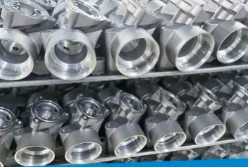
Gravity Die Casting relies on the natural force of gravity to fill the die, resulting in a straightforward and mechanically simple process. Unlike high-pressure methods, GDC does not use forceful injection, which significantly reduces turbulence during filling. This calmer process is ideal for medium-to-large aluminium components that require moderate complexity and strength, such as housings, brackets, and engine components.
Tooling for GDC is typically less complex than HPDC or LPDC. There are no pressurised systems, which lowers tooling and maintenance costs. However, thermal control is still critical. Effective die heating and cooling are necessary to maintain consistent flow and solidification, prevent hot spots, and avoid shrinkage porosity.
Because the fill is gravity-driven and slower, the process allows gases to escape more easily and can reduce the risk of trapped air and gas porosity. However, venting design remains important, especially in deep or intricate sections of the casting. Similarly, adequate feed systems and risers must be designed to compensate for shrinkage during solidification.
GDC’s slower fill and cooling times help produce a fine grain structure and improved mechanical integrity, particularly when combined with post-casting heat treatment. While not as fast or high-volume as HPDC, GDC offers excellent dimensional stability, surface finish, and structural soundness, making it a preferred choice for components where reliability and durability are key.
Overall, Gravity Die Casting strikes a balance between cost, quality, and mechanical performance, particularly suitable for moderate-volume production of non-ferrous alloy components.
Cycle Time, Cooling, and Tool Wear: Engineering Trade-offs
Poor cooling increases cycle time and tool stress, making it a hidden variable in die casting efficiency. If cooling channels are poorly designed, heat builds in the die, causing:
- Slower production due to longer wait times between cycles
- Thermal shock due to increased die stress
It is this thermal shock and fatigue which is often the leading cause of die failure in HPDC. Another reason why die casting tooling is so important.
As these dies are exposed to such varying temperatures – heating to 660 degrees and then cooling to 25 degrees – the design of them is crucial to distribute heat evenly to avoid hot spots that just accelerate failure.
When cooling, it’s important to do so in a uniform way to prevent internal defects. Cooling too fast and the part risks solidifying unevenly, but too slow and inefficiencies appear as cycle time increases.
One way to achieve uniform cooling is by using high-conductivity die materials to draw heat from thicker areas of the part and cooling channels on the die also aid this. Used strategically, they can reduce hot spots and help balance thermal gradients.
However they are designed, tools are only as good as their maintenance and inspection. Dies wear over time, causing edges to round off and surfaces to become worn, which leads to parts shifting out of desired tolerances.
Proactive maintenance such as polishing and preheating dies before use can ensure casting consistency.
Why Tooling Drives Repeatability and Dimensional Control
While dimension control and repeatability are often put front and centre of an engineer’s mind, the tooling itself is, in fact, the biggest influence on both. Your casting machines and materials can be as good as they need to be, but if the tooling is off, part variation will start to appear.
And when automotive programmes demand micron-level precision across thousands of castings, even small changes can have a huge impact.
Tooling is the foundation of accuracy, and if it’s stable and balanced, your parts will reflect that. Better tooling means fewer corrections are needed after the casting is complete, such as CNC reworks or heat treatments.
This consistency in design improves the downstream processes, such as robotic inspection, by preventing a pile-up of quality flags.
Tooling is a living part of the design process, which can be made better with past data to guide future designs and DFM strategies.
Design for Manufacture (DFM): Getting it Right Upstream
Effective collaboration during the early stages of tooling development can go a long way in preventing costly changes later down the line. Long before metal hits the die, simulation, design engineers, toolmakers, and production teams should all be involved in tooling design.
Without collaboration, an engineer could design a part with awkward parting lines, which is then created by a toolmaker, causing significant issues once production gets underway.
Working with a vertically integrated partner such as BCW Engineering streamlines the feedback loop between said toolmakers and machinists. With everyone working under the same roof, designs and specifications can be created in consultation with everyone, and any changes can be communicated quickly.
Within these designs, real-world constraints need to be factored in early, including:
- Simulation
- Press tonnage
- Ejector strength
- Die access
When all this is considered and factored in, it creates a tool that’s designed for smooth manufacturing, imbuing programme confidence in all key stakeholders.
The Sustainability Link: Scrap, Rework, and CO2e
When focusing on tool design, it can be easy to forget the wider benefits. One such ancillary benefit is to do with sustainability, a metric increasingly at the forefront of automotive Tier 1s and OEMs when considering suppliers.
At a basic level, creating a better tool means that fewer parts made will be rejected, and scrap rates remain low.
Poor tools create non-uniform parts that require further remachining to get them right. This increases CO2e, which has an upstream effect thanks to regulatory frameworks (i.e. CBAM) that require visibility on embedded carbon. First-time yield rates, total lifecycle emissions – two core components of carbon visibility – can be improved through optimised tools.
BCW uses closed-loop recycling systems and smart machining to mitigate environmental impacts. We prioritise this because we know that sustainability is no longer a nice optional extra. It is directly tied to new business.
Seven Key Questions Engineers Should Ask Their Casting Partners
Here are seven essential questions that should be asked by engineers looking to evaluate potential new suppliers.
- What’s the projected die life, and how is thermal fatigue managed?
- How do you monitor tool wear and maintain repeatability?
- Can you support iterative DFM collaboration before tooling is cut?
- What’s your approach to cooling channel design and thermal balance?
- How does your tooling design impact downstream CNC machining or surface finish?
- What data do you provide post-casting to support dimensional verification?
- Are you vertically integrated, or do you outsource toolmaking and casting separately?
The Right Tooling Design Equals Fewer Surprises and Better Parts
As we’ve shown, tooling design sets the tone for the rest of the casting programme.
Whether it’s HPDC, LPDC or GDC, small decisions have outsized impact on outcomes, and as automotive engineers are asked to do more with less, tooling becomes the strategic lever.
Partnering early with a vertically integrated supplier means engineers can form part of the tooling process rather than inherit the problems downstream